|
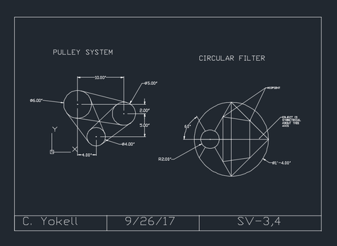
SV-3,4:
I originally was a bit overwhelmed with making this drawing, as I had no idea how to make the pulley system. I began with the pulley system and drew each of the circles at their respective distances from each other. Afterwards, I used tangent-tangent-radius to attach the lines to the respective locations to imitate the drawing that we were given. Next, I worked on the circular filter part of the drawing. This part was significantly easier in comparison to the pulley system. However, I still struggled at first because I did not know how to draw the line at an angle. I started it by drawing the large circle and the main line that cuts across the middle of the part. After that, I figured out how to draw a line at an angle. This is done by clicking the icon at the bottom right-hand corner of the screen that is the circle with the angle symbol drawn on it. I simply selected the 60 degree angle option and drew the line. At that point, I was able to draw the smaller circle at the intersection between the angled line and the horizontal line that crosses exactly at the center of the drawing. I chose this drawing for my website because, although I encountered issues, such as figuring out how to draw the pulley system as well as figuring out how to do the angle measurement on the circular filter part, I was able to overcome these obstacles and get a perfect score on the assignment. |
|
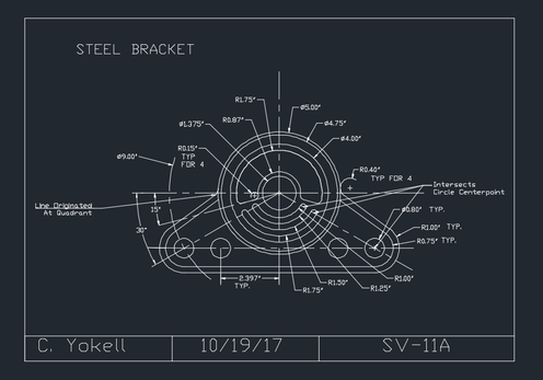
SV-11A
Originally, this drawing appeared very intimidating to me. In fact, I really struggled with making this drawing and had to ask for a significant amount of help. First, I started by making the circle in the center, and gradually worked my way out by making circles and using the trim command. For the bottom section, I drew the small circles at the appropriate points by lining the center of the circle up with the appropriate angles. After drawing the circles, I used the tangent-tangent radius command to connect the top and bottom parts. The main reason I had trouble with this drawing was the aspect of drawing the circles and trimming. The sheer amount of lines that appeared on the screen made it difficult to see where the circles were supposed to be trimmed. |
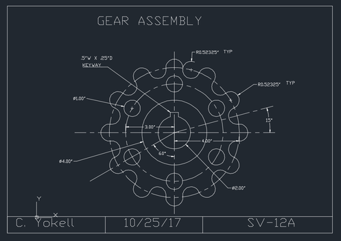
SV-12A
This project was easier to me than most because I had already used many of the commands necessary to complete the drawing throughout the year. Though I was intimidated by the complicated appearance of the drawing at first, I quickly was able to figure out how to complete it. For example, I used the array command in order to duplicate the circles around the outer edge so that I did no to have to waste a ton of time drawing each individual circle. I also used the trim command to get rid of the excess circles by following a simple in-out pattern as depicted in the drawing we were given. The one part I did have trouble on in this drawing however was the keyhole in the middle. However, I soon figured out how to do it. I drew a circle and then offset the center line and trimmed to make the keyhole.
This project was easier to me than most because I had already used many of the commands necessary to complete the drawing throughout the year. Though I was intimidated by the complicated appearance of the drawing at first, I quickly was able to figure out how to complete it. For example, I used the array command in order to duplicate the circles around the outer edge so that I did no to have to waste a ton of time drawing each individual circle. I also used the trim command to get rid of the excess circles by following a simple in-out pattern as depicted in the drawing we were given. The one part I did have trouble on in this drawing however was the keyhole in the middle. However, I soon figured out how to do it. I drew a circle and then offset the center line and trimmed to make the keyhole.
|
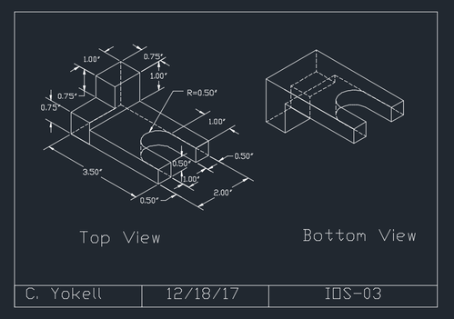
ISO-03
This drawing was one of the first that we did in the form of an isometric drawing. However, for some reason, I always found the ISO drawings easier than the SV drawings, because you could tell if you did something wrong because sections of the part would not connect properly. I started this drawing by sketching the base and then building the part up from there, starting from the back of the part and working my way to the front of the part. I drew the part with the circle in the top view last. This was challenging for me, though it should not have been. I had never drawn a circle in anything more than one dimension before, so it was something new to me. However, after soon realizing that all I had to do was type ellipse into the command bar and then put in the radius, I was good to go. Another challenging part of this ISO drawing was the bottom view. As with drawing ellipses, I had very limited exposure to drawing bottom views before this drawing. The process of mentally envisioning flipping the part upside down was originally very challenging for me. However, at this point in the ISO drawings, I began to get better at it. This was the first bottom view that I had been able to draw fully independently. |
|
|
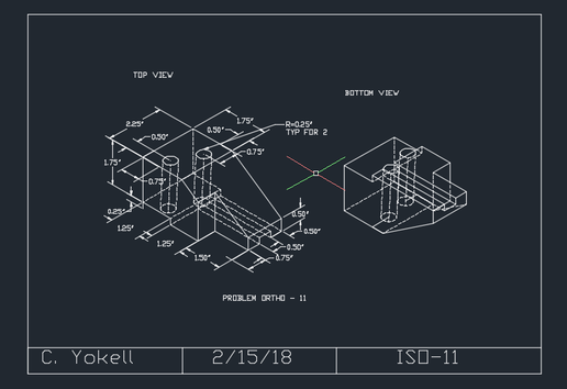
ISO-11
This ISO drawing was one of the last ones we did before we moved on to floor plans. This drawing focused on practicing sloped lines. I started this drawing like any other ISO drawing: by drawing the exterior base of the top view. From there, I built the part up and then drew the rectangular part on top of the back of the top view. To make the sloped lines, I simply drew a line connecting the top of the part to the bottom of the part. To save time, after I did this I simply offset the slope line at a specific distance to connect it to the other side of the part, and then I simply trimmed the excess lines. There were a few challenges for drawing this ISO. This was one of the first ISO's we had done that required us to put holes in. It took me a few minutes to turn on the right object snaps in order to draw the hidden lines that are connected the circle at the top and the bottom right. However, the most challenging part of this drawing was drawing the bottom view. This was also one of the first drawings where we had to draw the bottom view on our own. Mentally moving the object around was difficult for me at first, but by the end of this drawing, I began to get the hang of it. Also, drawing the holes in the right place on the bottom view was also difficult to do, but once I paid particular to how far away the holes were to specific features in the top view and then lined them up with those same features on the bottom view, it was fine.
This ISO drawing was one of the last ones we did before we moved on to floor plans. This drawing focused on practicing sloped lines. I started this drawing like any other ISO drawing: by drawing the exterior base of the top view. From there, I built the part up and then drew the rectangular part on top of the back of the top view. To make the sloped lines, I simply drew a line connecting the top of the part to the bottom of the part. To save time, after I did this I simply offset the slope line at a specific distance to connect it to the other side of the part, and then I simply trimmed the excess lines. There were a few challenges for drawing this ISO. This was one of the first ISO's we had done that required us to put holes in. It took me a few minutes to turn on the right object snaps in order to draw the hidden lines that are connected the circle at the top and the bottom right. However, the most challenging part of this drawing was drawing the bottom view. This was also one of the first drawings where we had to draw the bottom view on our own. Mentally moving the object around was difficult for me at first, but by the end of this drawing, I began to get the hang of it. Also, drawing the holes in the right place on the bottom view was also difficult to do, but once I paid particular to how far away the holes were to specific features in the top view and then lined them up with those same features on the bottom view, it was fine.
|
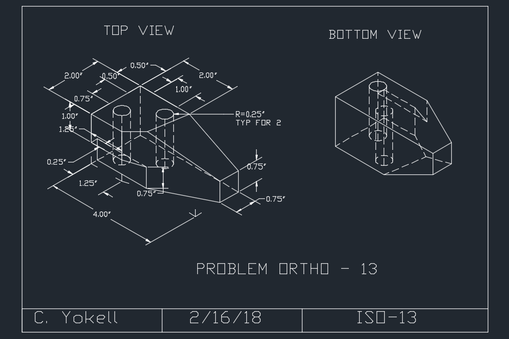
ISO 13
This ISO was one of the last that we drew, so I felt pretty confident while doing this one. I began by drawing the base on the top view and then building up from there. However, I came to a bit of a crossroads when I tried to draw the part of the object that is on the right side of the top view (the part that jots out of the side). In fact, I spent a couple classes trying to figure out this part alone. However, when I finally got the angles and measurements right after some peer help, I was able to simply connect the lines of the drawing and the top view was complete. On the other hand, the bottom view was much trickier. The weird shape of the top view made it extremely difficult to draw the bottom view. The dent in the part and the sloped lines caused me to mess up the bottom view a bit, since I kept confusing where lines were supposed to go. Also, the illusion that the bottom view was smaller than the top view also threw me off. Classroom
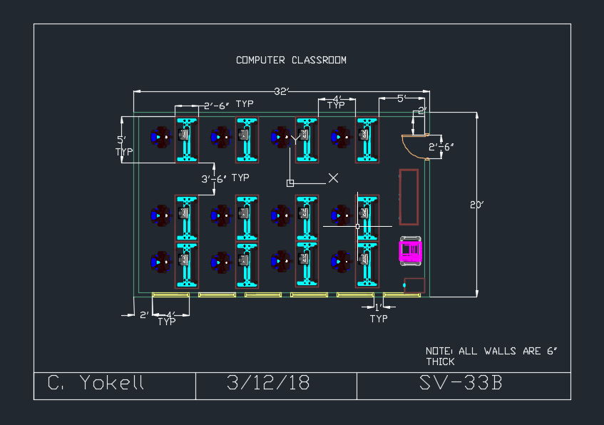
One of the first 3D drawings that we completed was drawing the classroom. Because this was one of the first 3D drawings that we did, the experience of drawing it was rough, to say the least. No matter which 3D drawing I drew, I always - for some strange reason - had trouble making the walls. I would always get confused about the math involved and lining it up the right way. It seemed that whenever I would think I had the measurements of the walls right, I would annotate them and then the measurements would be off and I would have to start all over again. Since this was the first time putting in equipment into the drawing, I was kind of lost during this process, but once I figured it out, it was very easy. Another difficult thing about this as one of the first 3D drawing is the fact that once you put equipment in, you have to go in another view to see if there are any desks or chairs flying in the air or sitting beneath the floor. Also, you had to make sure that the equipment, like the computers was sitting right on the desks too. This was a change from the other drawings we had done throughout the year, but I soon got used to it. Even though the project took me a relatively long time, I was still able to complete it and get a good grade on it. |
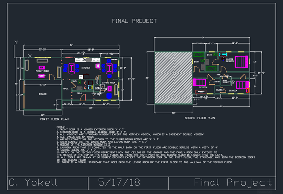
Final Project
This drawing was definitely my favorite that we had done all year, primarily because it allowed us to be creative and to draw something that we had imagined ourselves. I particularly enjoyed the aspect of this project that was creative as well as the ability to work at my own pace and to build what I wanted. I actually modeled my final project on my own house. I found this easier than simply making up the measurements and design of the house from scratch. I began with the first floor plan. Drawing the layout of the house was pretty easy except for drawing the half bath on the first floor. Because none of the other 3D drawings we had done had a room in the middle of the floor, it felt weird drawing it on my final project and it was a little difficult lining everything up to make sure the measurements were right. I also did not know how to draw the garage doors, but with a quick search I found two large openings for garage doors. Another challenge that came was that I did not remember to put in stairs until I was completely done with my drawing. For around 10 minutes, I was convinced that I would have to do the entire drawing over again in order to fit the stairs in. However, with help, I was able to come up with the idea of a spiral staircase so that I would not have to rearrange everything. After finishing the first floor, I had to work on the second floor. The second floor was significantly easier as there were less rooms and objects to put in. I used the hatch on the second floor to demonstrate that the ceiling for the space of the garage and the family room only extended up to the top of the first floor, signifying that the right side of the second floor was taller than the left side of the second floor. The only thing that was relatively difficult to complete on the second floor was lining up the measures of the second floor with the measures of the first floor. Overall, this was a fun but challenging project to do and actually demonstrated some real world applications of CAD.
This drawing was definitely my favorite that we had done all year, primarily because it allowed us to be creative and to draw something that we had imagined ourselves. I particularly enjoyed the aspect of this project that was creative as well as the ability to work at my own pace and to build what I wanted. I actually modeled my final project on my own house. I found this easier than simply making up the measurements and design of the house from scratch. I began with the first floor plan. Drawing the layout of the house was pretty easy except for drawing the half bath on the first floor. Because none of the other 3D drawings we had done had a room in the middle of the floor, it felt weird drawing it on my final project and it was a little difficult lining everything up to make sure the measurements were right. I also did not know how to draw the garage doors, but with a quick search I found two large openings for garage doors. Another challenge that came was that I did not remember to put in stairs until I was completely done with my drawing. For around 10 minutes, I was convinced that I would have to do the entire drawing over again in order to fit the stairs in. However, with help, I was able to come up with the idea of a spiral staircase so that I would not have to rearrange everything. After finishing the first floor, I had to work on the second floor. The second floor was significantly easier as there were less rooms and objects to put in. I used the hatch on the second floor to demonstrate that the ceiling for the space of the garage and the family room only extended up to the top of the first floor, signifying that the right side of the second floor was taller than the left side of the second floor. The only thing that was relatively difficult to complete on the second floor was lining up the measures of the second floor with the measures of the first floor. Overall, this was a fun but challenging project to do and actually demonstrated some real world applications of CAD.
